


Blogs
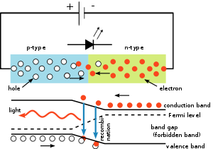
The inner workings of an LED, showing circuit (top) and band diagram (bottom)
A P-N junction can convert absorbed light energy into a proportional electric current. The same process is reversed here (i.e. the P-N junction emits light when electrical energy is applied to it).
This phenomenon is generally called electroluminescence, which can be defined as the emission of light from a semi-conductor under the influence of an electric field. The charge carriers recombine in a forward-biased P-N junction as the electrons cross from the N-region and recombine with the holes existing in the P-region. Free electrons are in the conduction band of energy levels, while holes are in the valence energy band. Thus the energy level of the holes will be lesser than the energy levels of the electrons. Some portion of the energy must be dissipated in order to recombine the electrons and the holes. This energy is emitted in the form of heat and light.
The inner workings of an LED, showing circuit.
The electrons dissipate energy in the form of heat for silicon and germanium diodes but in gallium arsenide phosphide (GaAsP) and gallium phosphide (GaP) semiconductors, the electrons dissipate energy by emitting photons. If the semiconductor is translucent, the junction becomes the source of light as it is emitted, thus becoming a light-emitting diode, but when the junction is reverse biased no light will be produced by the LED and, on the contrary, the device may also be damaged.
Technology
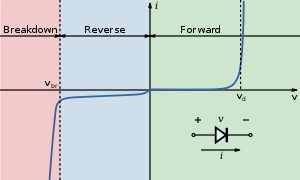
I-V diagram for a diode. An LED will begin to emit light when more than 2 or 3 volts is applied to it.
Physics
The LED consists of a chip of semiconducting material doped with impurities to create a p-n junction. As in other diodes, current flows easily from the p-side, or anode, to the n-side, or cathode, but not in the reverse direction. Charge-carriers—electrons and holes—flow into the junction from electrodes with different voltages. When an electron meets a hole, it falls into a lower energy level and releases energy in the form of a photon.
The wavelength of the light emitted, and thus its color, depends on the band gap energy of the materials forming the p-n junction. In silicon or germanium diodes, the electrons and holes usually recombine by a non-radiative transition, which produces no optical emission, because these are indirect band gap materials. The materials used for the LED have a direct band gap with energies corresponding to near-infrared, visible, or near-ultraviolet light.
LED development began with infrared and red devices made with gallium arsenide. Advances in materials science have enabled making devices with ever-shorter wavelengths, emitting light in a variety of colors.
LEDs are usually built on an n-type substrate, with an electrode attached to the p-type layer deposited on its surface. P-type substrates, while less common, occur as well. Many commercial LEDs, especially GaN/InGaN, also use sapphire substrate.
Most materials used for LED production have very high refractive indices. This means that much of the light will be reflected back into the material at the material/air surface interface. Thus, light extraction in LEDs is an important aspect of LED production, subject to much research and development.
Refractive index

Idealized example of light emission cones in a semiconductor, for a single point-source emission zone. The left illustration is for a fully translucent wafer, while the right illustration shows the half-cones formed when the bottom layer is fully opaque. The light is actually emitted equally in all directions from the point-source, so the areas between the cones shows the large amount of trapped light energy that is wasted as heat.

The light emission cones of a real LED wafer are far more complex than a single point-source light emission. The light emission zone is typically a two-dimensional plane between the wafers.
Every atom across this plane has an individual set of emission cones. Drawing the billions of overlapping cones is impossible, so this is a simplified diagram showing the extents of all the emission cones combined. The larger side cones are clipped to show the interior features and reduce image complexity; they would extend to the opposite edges of the two-dimensional emission plane.
Bare uncoated semiconductors such as silicon exhibit a very high refractive index relative to open air, which prevents passage of photons arriving at sharp angles relative to the air-contacting surface of the semiconductor due to total internal reflection. This property affects both the light-emission efficiency of LEDs as well as the light-absorption efficiency of photovoltaic cells. The refractive index of silicon is 3.96 (at 590 nm), while air is 1.0002926.
In general, a flat-surface uncoated LED semiconductor chip will emit light only perpendicular to the semiconductor's surface, and a few degrees to the side, in a cone shape referred to as the light cone, cone of light, or the escape cone. The maximum angle of incidence is referred to as the critical angle. When this angle is exceeded, photons no longer escape the semiconductor but are instead reflected internally inside the semiconductor crystal as if it were a mirror.
Internal reflections can escape through other crystalline faces, if the incidence angle is low enough and the crystal is sufficiently transparent to not re-absorb the photon emission. But for a simple square LED with 90-degree angled surfaces on all sides, the faces all act as equal angle mirrors. In this case most of the light can not escape and is lost as waste heat in the crystal.
A convoluted chip surface with angled facets similar to a jewel or fresnel lens can increase light output by allowing light to be emitted perpendicular to the chip surface while far to the sides of the photon emission point.
The ideal shape of a semiconductor with maximum light output would be a microsphere with the photon emission occurring at the exact center, with electrodes penetrating to the center to contact at the emission point. All light rays emanating from the center would be perpendicular to the entire surface of the sphere, resulting in no internal reflections. A hemispherical semiconductor
would also work, with the flat back-surface serving as a mirror to back-scattered photons.
Transition Coatings
After the doping of the wafer, it is cut apart into individual dies. Each die is commonly called a chip.
Many LED semiconductor chips are encapsulated or potted in clear or colored molded plastic shells. The plastic shell has three purposes:
1. Mounting the semiconductor chip in devices is easier to accomplish.
2. The tiny fragile electrical wiring is physically supported and protected from damage.
3. The plastic acts as a refractive intermediary between the relatively high-index
semiconductor and low-index open air.
The third feature helps to boost the light emission from the semiconductor by acting as a diffusing lens, allowing light to be emitted at a much higher angle of incidence from the light cone than the bare chip is able to emit alone.
Efficiency and operational parameters
Typical indicator LEDs are designed to operate with no more than 30–60 milliwatts (mW) of electrical power. Around 1999, Philips Lumileds introduced power LEDs capable of continuous use at one watt. These LEDs used much larger semiconductor die sizes to handle the large power inputs. Also, the semiconductor dies were mounted onto metal slugs to allow for heat removal
from the LED die.
One of the key advantages of LED-based lighting sources is high luminous efficacy. White LEDs quickly matched and overtook the efficacy of standard incandescent lighting systems. In 2002, Lumileds made five-watt LEDs available with luminous efficacy of 18–22 lumens per watt (lm/W). For comparison, a conventional incandescent light bulb of 60–100 watts emits around 15 lm/W, and standard fluorescent lights emit up to 100 lm/W.
As of 2012, Philips had achieved the following efficacies for each color.[52] The efficiency values show the physics – light power out per electrical power in. The lumen-per-watt efficacy value includes characteristics of the human eye, and is derived using the luminosity function.
|
Color |
Wavelength range (nm) |
Typical efficiency coefficient |
Typical |
|
|---|---|---|---|---|
| Red | 620 < λ < 645 | 0.39 | 72 | |
| Red-orange | 610 < λ < 620 | 0.29 | 98 | |
| Green | 520 < λ < 550 | 0.15 | 93 | |
| Cyan | 490 < λ < 520 | 0.26 | 75 | |
| Blue | 460 < λ < 490 | 0.35 | 37 |
In September 2003, a new type of blue LED was demonstrated by Cree that consumes 24 mW at 20 milliamperes (mA). This produced a commercially packaged white light giving 65 lm/W at 20 mA, becoming the brightest white LED commercially available at the time, and more than four times as efficient as standard incandescents. In 2006, they demonstrated a prototype with a
record white LED luminous efficacy of 131 lm/W at 20 mA. Nichia Corporation has developed a white LED with luminous efficacy of 150 lm/W at a forward current of 20 mA. Cree's XLamp XM-L LEDs, commercially available in 2011, produce 100 lm/W at their full power of 10 W, and up to 160 lm/W at around 2 W input power. In 2012, Cree announced a white LED giving 254 lm/W, and 303 lm/W in March 2014. Practical general lighting needs high-power LEDs, of one watt or more. Typical operating currents for such devices begin at 350 mA.
These efficiencies are for the light-emitting diode only, held at low temperature in a lab. Since LEDs installed in real fixtures operate at higher temperature and with driver losses, real-world efficiencies are much lower. United States Department of Energy (DOE) testing of commercial LED lamps designed to replace incandescent lamps or CFLs showed that average efficacy was still about 46 lm/W in 2009 (tested performance ranged from 17 lm/W to 79 lm/W).
Efficiency Droop
Efficiency droop is the decrease in luminous efficiency of LEDs as the electric current increases above tens of milliamperes.
This effect was initially theorized to be related to elevated temperatures. Scientists proved the opposite to be true that, although the life of an LED would be shortened, the efficiency droop is less severe at elevated temperatures.
The mechanism causing efficiency droop was identified in 2007 as Auger recombination, which was taken with mixed reaction. In 2013, a study
confirmed Auger recombination as the cause of efficiency droop.
In addition to being less efficient, operating LEDs at higher electric currents creates higher heat levels which compromise the lifetime of the LED. Because of this increased heating at higher currents, high-brightness LEDs have an industry standard of operating at only 350 mA, which is a compromise between light output, efficiency, and longevity.
Possible solutions
Instead of increasing current levels, luminance is usually increased by combining multiple LEDs in one bulb. Solving the problem of efficiency droop would mean that household LED light bulbs would need fewer LEDs, which would significantly reduce costs.
Researchers at the U.S. Naval Research Laboratory have found a way to lessen the efficiency droop. They found that the droop arises from non-radiative Auger recombination of the injected carriers. They created quantum wells with a soft confinement potential to lessen the non-radiative Auger processes.
Researchers at Taiwan National Central University and Epistar Corp are developing a way to lessen the efficiency droop by using ceramic aluminium nitride (AlN) substrates, which are more thermally conductive than the commercially used sapphire. The higher thermal conductivity reduces self-heating effects.
Lifetime and Failure
Solid-state devices such as LEDs are subject to very limited wear and tear if operated at low currents and at low temperatures. Typical lifetimes quoted are 25,000 to 100,000 hours, but heat and current settings can extend or shorten this time significantly.
The most common symptom of LED (and diode laser) failure is the gradual lowering of light output and loss of efficiency. Sudden failures, although rare, can also occur. Early red LEDs were notable for their short service life. With the development of high-power LEDs the devices are subjected to higher junction temperatures and higher current densities than traditional devices. This causes stress on the material and may cause early light-output degradation. To quantitatively classify useful lifetime in a standardized manner it has been suggested to use L70 or L50, which are the runtimes (typically given in thousands of hours) at which a given LED reaches 70% and 50% of initial light output, respectively.
LED performance is temperature dependent. Most manufacturers' published ratings of LEDs are for an operating temperature of 25 °C (77 °F). LEDs used outdoors, such as traffic signals or in-pavement signal lights, and that are used in climates where the temperature within the light fixture gets very high, could result in low signal intensities or even failure.
Since LED efficacy is inversely proportional to operating temperature, LED technology is well suited for supermarket freezer lighting.[68][69][70] Because LEDs produce less waste heat than incandescent lamps, their use in freezers can save on refrigeration costs as well. However, they may be more susceptible to frost and snow buildup than incandescent lamps, so some LED lighting systems have been designed with an added heating circuit. Additionally, research has developed heat sink technologies that will transfer heat produced within the junction to appropriate areas of the light fixture.
Colors and materials
Conventional LEDs are made from a variety of inorganic semiconductor materials. The following table shows the available colors with wavelength range, voltage drop and material:
|
Color |
Wavelength [nm] |
Voltage drop [ΔV] |
Semiconductor material |
|
|---|---|---|---|---|
| Infrared | λ > 760 | ΔV < 1.63 | Gallium arsenide (GaAs) Aluminium gallium arsenide (AlGaAs) |
|
| Red | 610 < λ < 760 | 1.63 < ΔV < 2.03 | Aluminium gallium arsenide (AlGaAs) Gallium arsenide phosphide (GaAsP) Aluminium gallium indium phosphide (AlGaInP) Gallium(III) phosphide (GaP) |
|
| Orange | 590 < λ < 610 | 2.03 < ΔV < 2.10 | Gallium arsenide phosphide (GaAsP) Aluminium gallium indium phosphide (AlGaInP) Gallium(III) phosphide (GaP) |
|
| Yellow | 570 < λ < 590 | 2.10 < ΔV < 2.18 | Gallium arsenide phosphide (GaAsP) Aluminium gallium indium phosphide (AlGaInP) Gallium(III) phosphide (GaP) |
|
| Green | 500 < λ < 570 | 1.9 < ΔV < 4.0 | Traditional green: Gallium(III) phosphide (GaP) Aluminium gallium indium phosphide (AlGaInP) Aluminium gallium phosphide (AlGaP) Pure green: Indium gallium nitride (InGaN) / Gallium(III) nitride (GaN) |
|
| Blue | 450 < λ < 500 | 2.48 < ΔV < 3.7 | Zinc selenide (ZnSe) Indium gallium nitride (InGaN) Silicon carbide (SiC) as substrate Silicon (Si) as substrate—under development |
|
| Violet | 400 < λ < 450 | 2.76 < ΔV < 4.0 | Indium gallium nitride (InGaN) | |
| Purple | Multiple types | 2.48 < ΔV < 3.7 | Dual blue/red LEDs, blue with red phosphor, or white with purple plastic |
|
| Ultraviolet | λ < 400 | 3 < ΔV < 4.1 | Indium gallium nitride (InGaN) (385-400 nm)
Diamond (235 nm) |
|
| Pink | Multiple types | ΔV ~ 3.3 | Blue with one or two phosphor layers, yellow with red, orange or pink phosphor added afterwards, white with pink plastic, |
|
| White | Broad spectrum | 2.8 < ΔV < 4.2 | Cool / Pure White: Blue/UV diode with yellow phosphor Warm White: Blue diode with orange phosphor |

Blue LEDs
Blue and Ultraviolet
The first blue-violet LED using magnesium-doped gallium nitride was made at Stanford University in 1972 by Herb Maruska and Wally Rhines, doctoral students in materials science and engineering. At the time Maruska was on leave from RCA Laboratories, where he collaborated with Jacques Pankove on related work. In 1971, the year after Maruska left for Stanford, his RCA colleagues Pankove and Ed Miller demonstrated the first blue electroluminescence from zinc-doped gallium nitride, though the subsequent device Pankove and
Miller built, the first actual gallium nitride light-emitting diode, emitted green light.
In 1974 the U.S. Patent Office awarded Maruska, Rhines and Stanford professor David Stevenson a patent for their work in 1972 (U.S. Patent US3819974 A) and today magnesium-doping of gallium nitride continues to be the basis for all commercial blue LEDs and laser diodes. These devices built in the early 1970s had too little light output to be of practical use and research into gallium nitride devices slowed. In August 1989, Cree introduced the first commercially available
blue LED based on the indirect bandgap semiconductor, silicon carbide (SiC).[84] SiC LEDs had very low efficiency, no more than about 0.03%, but did emit in the blue portion of the visible light spectrum.
In the late 1980s, key breakthroughs in GaN epitaxial growth and p-type doping ushered in the modern era of GaN-based optoelectronic devices. Building upon this foundation, Theodore Moustakas at Boston University patented a method for producing high-brightness blue LEDs using a new two-step process.[86] Two years later, in 1993, high-brightness blue LEDs were demonstrated again by Shuji Nakamura of Nichia Corporation using a gallium nitride growth process similar to Moustakas's.[87] Both Moustakas and Nakamura were issued separate patents, which confused the issue of who was the original inventor (partly because although Moustakas invented his first, Nakamura filed first).[citation needed] This new development revolutionized LED lighting, making high-power blue light sources practical, leading to the development of
technologies like Blu-ray, as well as allowing the bright high resolution screens of modern tablets and phones.
Nakamura was awarded the 2006 Millennium Technology Prize for his invention. Nakamura, Hiroshi Amano and Isamu Akasaki were awarded the Nobel Prize in Physics in 2014 for the invention of the blue LED.[89][90][91] In 2015, a US court ruled that three companies (i.e. the litigants who had not previously settled out of court) that had licensed Nakamura's patents for production in the United States had infringed Moustakas's prior patent, and ordered them to pay licensing fees of not less than 13 million USD.
By the late 1990s, blue LEDs became widely available. They have an active region consisting of one or more InGaN quantum wells sandwiched between thicker layers of GaN, called cladding layers. By varying the relative In/Ga fraction in the InGaN quantum wells, the light emission can in theory be varied from violet to amber. Aluminium gallium nitride (AlGaN) of varying Al/Ga
fraction can be used to manufacture the cladding and quantum well layers for ultraviolet LEDs, but these devices have not yet reached the level of efficiency and technological maturity of InGaN/GaN blue/green devices. If un-alloyed GaN is used in this case to form the active quantum well layers, the device will emit near-ultraviolet light with a peak wavelength centred around 365 nm. Green LEDs manufactured from the InGaN/GaN system are far more efficient and brighter than green LEDs produced with non-nitride material systems, but practical devices
still exhibit efficiency too low for high-brightness applications.[citation needed]
With nitrides containing aluminium, most often AlGaN and AlGaInN, even shorter wavelengths are achievable. Ultraviolet LEDs in a range of wavelengths are becoming available on the market. Near-UV emitters at wavelengths around 375–395 nm are already cheap and often encountered, for example, as black light lamp replacements for inspection of anti-counterfeiting UV watermarks in some documents and paper currencies. Shorter-wavelength diodes, while
substantially more expensive, are commercially available for wavelengths down to 240 nm.
As the photosensitivity of microorganisms approximately matches the absorption spectrum of DNA, with a peak at about 260 nm, UV LED emitting at 250–270 nm are to be expected in prospective disinfection and sterilization devices. Recent research has shown that commercially available UVA LEDs (365 nm) are already effective disinfection and sterilization devices.
UV-C wavelengths were obtained in laboratories using aluminium nitride (210 nm),[76] boron nitride (215 nm)[74][75] and diamond (235 nm).[73]
RGB

RGB-SMD-LED
RGB LEDs consist of one red, one green, and one blue LED. By independently adjusting each of the three, RGB LEDs are capable of producing a wide color gamut. Unlike dedicated-color LEDs, however, these obviously do not produce pure wavelengths. Moreover, such modules as commercially available are often not optimized for smooth color mixing.
White
There are two primary ways of producing white light-emitting diodes (WLEDs), LEDs that generate high-intensity white light. One is to use individual LEDs that emit three primary colors—red, green, and blue—and then mix all the colors to form white light. The other is to use a phosphor material to convert monochromatic light from a blue or UV LED to broad-spectrum white light, much in the same way a fluorescent light bulb works. It is important to note that the 'whiteness' of the light produced is essentially engineered to suit the human eye, and depending on the situation it may not always be appropriate to think of it as white light.
There are three main methods of mixing colors to produce white light from an LED:
* blue LED + green LED + red LED (color mixing; can be used as backlighting for
displays)
* near-UV or UV LED + RGB phosphor (an LED producing light with a wavelength
shorter than blue's is used to excite an RGB phosphor)
* blue LED + yellow phosphor (two complementary colors combine to form white light;
more efficient than first two methods and more commonly used)[96]
Because of metamerism, it is possible to have quite different spectra that appear white. However,
the appearance of objects illuminated by that light may vary as the spectrum varies.
RGB systems
Combined spectral curves for blue, yellow-green, and high-brightness red solid-state semiconductor LEDs. FWHM spectral bandwidth is approximately 24–27 nm for all three colors.


RGB LED
White light can be formed by mixing differently colored lights; the most common method is to use red, green, and blue (RGB). Hence the method is called multi-color white LEDs (sometimes referred to as RGB LEDs). Because these need electronic circuits to control the blending and diffusion of different colors, and because the individual color LEDs typically have slightly different emission patterns (leading to variation of the color depending on direction) even if they
are made as a single unit, these are seldom used to produce white lighting. Nonetheless, this method has many applications because of the flexibility of mixing different colors, and in principle, this mechanism also has higher quantum efficiency in producing white light.
There are several types of multi-color white LEDs: di-, tri-, and tetrachromatic white LEDs. Several key factors that play among these different methods, include color stability, color rendering capability, and luminous efficacy. Often, higher efficiency will mean lower color rendering, presenting a trade-off between the luminous efficacy and color rendering. For example, the dichromatic white LEDs have the best luminous efficacy (120 lm/W), but the lowest color rendering capability. However, although tetrachromatic white LEDs have excellent color rendering capability, they often have poor luminous efficacy. Trichromatic white LEDs are in between, having both good luminous efficacy (>70 lm/W) and fair color rendering capability.
One of the challenges is the development of more efficient green LEDs. The theoretical maximum for green LEDs is 683 lumens per watt but as of 2010 few green LEDs exceed even 100 lumens per watt. The blue and red LEDs get closer to their theoretical limits.
Multi-color LEDs offer not merely another means to form white light but a new means to form light of different colors. Most perceivable colors can be formed by mixing different amounts of three primary colors. This allows precise dynamic color control. As more effort is devoted to investigating this method, multi-color LEDs should have profound influence on the fundamental method that we use to produce and control light color. However, before this type of LED can play a role on the market, several technical problems must be solved. These include that this type of LED's emission power decays exponentially with rising temperature, resulting in a substantial change in color stability. Such problems inhibit and may preclude industrial use.
Thus, many new package designs aimed at solving this problem have been proposed and their results are now being reproduced by researchers and scientists.
Correlated color temperature (CCT) dimming for LED technology is regarded as a difficult task, since binning, age and temperature drift effects of LEDs change the actual color value output.
Feedback loop systems are used for example with color sensors, to actively monitor and control the color output of multiple color mixing LEDs.
Phosphor-based LEDs
Spectrum of a white LED showing blue light directly emitted by the GaN-based LED (peak at about 465 nm) and the more broadband Stokes-shifted light emitted by the Ce3+:YAG phosphor, which emits at roughly 500–700 nm
This method involves coating LEDs of one color (mostly blue LEDs made of InGaN) with phosphors of different colors to form white light; the resultant LEDs are called phosphor-based or phosphor-converted white LEDs (pcLEDs). A fraction of the blue light undergoes the Stokes shift being transformed from shorter wavelengths to longer. Depending on the color of the original LED, phosphors of different colors can be employed. If several phosphor layers of
distinct colors are applied, the emitted spectrum is broadened, effectively raising the color rendering index (CRI) value of a given LED.

Spectrum of a white LED showing blue light directly emitted by the GaN-based LED (peak at about 465 nm) and the more broadband Stokes-shifted light emitted by the Ce3+:YAG phosphor, which emits at roughly 500–700 nm
Phosphor-based LED efficiency losses are due to the heat loss from the Stokes shift and also other phosphor-related degradation issues. Their luminous efficacies compared to normal LEDs depend on the spectral distribution of the resultant light output and the original wavelength of the LED itself. For example, the luminous efficacy of a typical YAG yellow phosphor based white LED ranges from 3 to 5 times the luminous efficacy of the original blue LED because of the
human eye's greater sensitivity to yellow than to blue (as modeled in the luminosity function).
Due to the simplicity of manufacturing the phosphor method is still the most popular method for making high-intensity white LEDs. The design and production of a light source or light fixture using a monochrome emitter with phosphor conversion is simpler and cheaper than a complex RGB system, and the majority of high-intensity white LEDs presently on the market are manufactured using phosphor light conversion.
Among the challenges being faced to improve the efficiency of LED-based white light sources is the development of more efficient phosphors. As of 2010, the most efficient yellow phosphor is still the YAG phosphor, with less than 10% Stoke shift loss. Losses attributable to internal optical losses due to re-absorption in the LED chip and in the LED packaging itself account
typically for another 10% to 30% of efficiency loss. Currently, in the area of phosphor LED development, much effort is being spent on optimizing these devices to higher light output and higher operation temperatures. For instance, the efficiency can be raised by adapting better package design or by using a more suitable type of phosphor. Conformal coating process is frequently used to address the issue of varying phosphor thickness.
Some phosphor-based white LEDs encapsulate InGaN blue LEDs inside phosphor-coated epoxy. Alternatively, the LED might be paired with a remote phosphor, a preformed polycarbonate piece coated with the phosphor material. Remote phosphors provide more diffuse light, which is desirable for many applications. Remote phosphor designs are also more tolerant of variations in
the LED emissions spectrum. A common yellow phosphor material is cerium-doped yttrium aluminium garnet (Ce3+:YAG).
White LEDs can also be made by coating near-ultraviolet (NUV) LEDs with a mixture of high-efficiency europium-based phosphors that emit red and blue, plus copper and aluminium-doped zinc sulfide (ZnS:Cu, Al) that emits green. This is a method analogous to the way fluorescent lamps work. This method is less efficient than blue LEDs with YAG:Ce phosphor, as the Stokes shift is larger, so more energy is converted to heat, but yields light with better spectral
characteristics, which render color better. Due to the higher radiative output of the ultraviolet LEDs than of the blue ones, both methods offer comparable brightness.
A concern is that UV light may leak from a malfunctioning light source and cause harm to human eyes or skin.
Other white LEDs
Another method used to produce experimental white light LEDs used no phosphors at all and was based on homoepitaxially grown zinc selenide (ZnSe) on a ZnSe substrate that simultaneously emitted blue light from its active region and yellow light from the substrate.
A new style of wafers composed of gallium-nitride-on-silicon (GaN-on-Si) is being used to produce white LEDs using 200-mm silicon wafers. This avoids the typical costly sapphire substrate in relatively small 100- or 150-mm wafer sizes. The sapphire apparatus must be coupled with a mirror-like collector to reflect light that would otherwise be wasted. It is predicted that by 2020, 40% of all GaN LEDs will be made with GaN-on-Si. Manufacturing large sapphire material is difficult, while large silicon material is cheaper and more abundant.
LED companies shifting from using sapphire to silicon should be a minimal investment.
Organic light-emitting diodes (OLEDs)

Orange light-emitting diode
In an organic light-emitting diode (OLED), the electroluminescent material comprising the emissive layer of the diode is an organic compound. The organic material is electrically conductive due to the delocalization of pi electrons caused by conjugation over all or part of the molecule, and the material therefore functions as an organic semiconductor. The organic materials can be small organic molecules in a crystalline phase, or polymers.
The potential advantages of OLEDs include thin, low-cost displays with a low driving voltage, wide viewing angle, and high contrast and color gamut. Polymer LEDs have the added benefit of printable and flexible displays. OLEDs have been used to make visual displays for portable electronic devices such as cellphones, digital cameras, and MP3 players while possible future uses include lighting and televisions.
Quantum dot LEDs
Quantum dots (QD) are semiconductor nanocrystals that possess unique optical
properties. Their emission color can be tuned from the visible throughout the infrared spectrum. This allows quantum dot LEDs to create almost any color on the CIE diagram. This provides more color options and better color rendering than white LEDs since the emission spectrum is much narrower, characteristic of quantum confined states. There are two types of schemes for QD excitation. One uses photo excitation with a primary light source LED (typically blue or UV LEDs are used). The other is direct electrical excitation first demonstrated by Alivisatos et al.
One example of the photo-excitation scheme is a method developed by Michael Bowers, at Vanderbilt University in Nashville, involving coating a blue LED with quantum dots that glow white in response to the blue light from the LED. This method emits a warm, yellowish-white light similar to that made by incandescent light bulbs. Quantum dots are also being considered for use in white light-emitting diodes in liquid crystal display (LCD) televisions.
In February 2011 scientists at PlasmaChem GmbH were able to synthesize quantum dots for LED applications and build a light converter on their basis, which was able to efficiently convert light from blue to any other color for many hundred hours. Such QDs can be used to emit visible or near infrared light of any wavelength being excited by light with a shorter wavelength.
The structure of QD-LEDs used for the electrical-excitation scheme is similar to basic design of OLEDs. A layer of quantum dots is sandwiched between layers of electron-transporting and hole-transporting materials. An applied electric field causes electrons and holes to move into the quantum dot layer and recombine forming an exciton that excites a QD. This scheme is commonly studied for quantum dot display. The tunability of emission wavelengths and narrow bandwidth is also beneficial as excitation sources for fluorescence imaging. Fluorescence near-field scanning optical microscopy (NSOM) utilizing an integrated QD-LED has been demonstrated.
In February 2008, a luminous efficacy of 300 lumens of visible light per watt of radiation (not per electrical watt) and warm-light emission was achieved by using nanocrystals.
Types
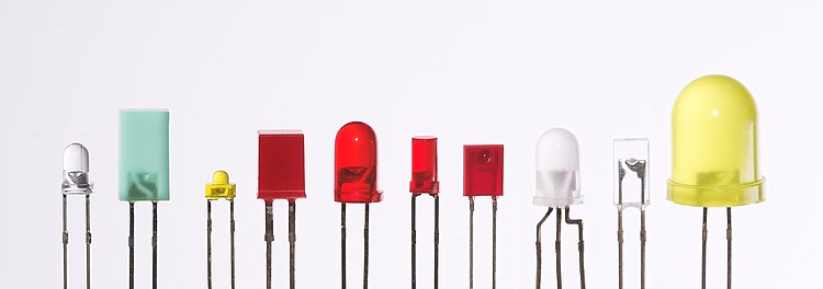
LEDs are produced in a variety of shapes and sizes. The color of the plastic lens is often the same as the actual color of light emitted, but not always. For instance, purple plastic is often used for infrared LEDs, and most blue devices have colorless housings. Modern high-power LEDs such as those used for lighting and backlighting are generally found in surface-mount technology
(SMT) packages (not shown).
The main types of LEDs are miniature, high-power devices and custom designs such as alphanumeric or multi-color.
Miniature
Photo of miniature surface mount LEDs in most common sizes. They can be much smaller than a traditional 5 mm lamp type LED which is shown on the upper left corner.
Very small (1.6x1.6x0.35 mm) red, green, and blue surface mount miniature LED package with gold wire bonding details.
These are mostly single-die LEDs used as indicators, and they come in various sizes from 2 mm to 8 mm, through-hole and surface mount packages. They usually do not use a separate heat sink. Typical current ratings ranges from around 1 mA to above 20 mA. The small size sets a natural upper boundary on power consumption due to heat caused by the high current density and need for a heat sink. Often daisy chained as used in LED tapes.
Common package shapes include round, with a domed or flat top, rectangular with a flat top (as used in bar-graph displays), and triangular or square with a flat top. The encapsulation may also be clear or tinted to improve contrast and viewing angle.
Researchers at the University of Washington have invented the thinnest LED. It is made of two-dimensional (2-D) flexible materials. It is three atoms thick, which is 10 to 20 times thinner than three-dimensional (3-D) LEDs and is also 10,000 times smaller than the thickness of a human hair. These 2-D LEDs are going to make it possible to create smaller, more energy-efficient lighting, optical communication and nano lasers.
There are three main categories of miniature single die LEDs:
Low-current
Typically rated for 2 mA at around 2 V (approximately 4 mW consumption)
Standard
20 mA LEDs (ranging from approximately 40 mW to 90 mW) at around:
* 1.9 to 2.1 V for red, orange, yellow, and traditional green
* 3.0 to 3.4 V for pure green and blue
* 2.9 to 4.2 V for violet, pink, purple and white
Ultra-high-output
20 mA at approximately 2 or 4–5 V, designed for viewing in direct sunlight
5 V and 12 V LEDs are ordinary miniature LEDs that incorporate a suitable series resistor for
direct connection to a 5 V or 12 V supply.
High-power
High-power light-emitting diodes attached to an LED star base (Luxeon, Lumileds)
See also: Solid-state lighting, LED lamp, and Thermal management of high-power LEDs
High-power LEDs (HP-LEDs) or high-output LEDs (HO-LEDs) can be driven at currents from hundreds of mA to more than an ampere, compared with the tens of mA for other LEDs. Some can emit over a thousand lumens. LED power densities up to 300 W/cm2 have been achieved. Since overheating is destructive, the HP-LEDs must be mounted on a heat sink to allow for heat dissipation. If the heat from a HP-LED is not removed, the device will fail in seconds. One HP-LED can often replace an incandescent bulb in a flashlight, or be set in an array to form a powerful LED lamp.
Some well-known HP-LEDs in this category are the Nichia 19 series, Lumileds Rebel Led, Osram Opto Semiconductors Golden Dragon, and Cree X-lamp. As of September 2009, some HP-LEDs manufactured by Cree now exceed 105 lm/W.
Examples for Haitz's law, which predicts an exponential rise in light output and efficacy of LEDs over time, are the CREE XP-G series LED which achieved 105 lm/W in 2009 and the Nichia 19 series with a typical efficacy of 140 lm/W, released in 2010.
AC driven
LEDs have been developed by Seoul Semiconductor that can operate on AC power without the need for a DC converter. For each half-cycle, part of the LED emits light and part is dark, and this is reversed during the next half-cycle. The efficacy of this type of HP-LED is typically 40 lm/W. A large number of LED elements in series may be able to operate directly from line voltage. In 2009, Seoul Semiconductor released a high DC voltage LED, named as 'Acrich MJT',
capable of being driven from AC power with a simple controlling circuit. The low-power dissipation of these LEDs affords them more flexibility than the original AC LED design.
Application-specific variations
Flashing - Flashing LEDs are used as attention seeking indicators without requiring external electronics. Flashing LEDs resemble standard LEDs but they contain an integrated multivibrator circuit that causes the LED to flash with a typical period of one second. In diffused lens LEDs, this circuit is visible as a small black dot. Most flashing LEDs emit light of one color, but more sophisticated devices can flash between multiple colors and even fade through a color sequence using RGB color mixing.
Bi-color - Bi-color LEDs contain two different LED emitters in one case. There are two types of these. One type consists of two dies connected to the same two leads antiparallel to each other. Current flow in one direction emits one color, and current in the opposite direction emits the other color. The other type consists of two dies with separate leads for both dies and another lead for common anode or cathode, so that they can be controlled independently.
Tri-color - Tri-color LEDs contain three different LED emitters in one case. Each emitter is connected to a separate lead so they can be controlled independently. A four-lead arrangement is typical with one common lead (anode or cathode) and an additional lead for each color.
RGB - RGB LEDs are tri-color LEDs with red, green, and blue emitters, in general using a four-wire connection with one common lead (anode or cathode). These LEDs can have either common positive or common negative leads. Others however, have only two leads (positive and negative) and have a built-in tiny electronic control unit.
Decorative-multicolor - Decorative-multicolor LEDs incorporate several emitters of different colors supplied by only two lead-out wires. Colors are switched internally by varying the supply voltage.
Alphanumeric - Alphanumeric LEDs are available in seven-segment, starburst and dot-matrix format. Seven-segment displays handle all numbers and a limited set of letters. Starburst displays can display all letters. Dot-matrix displays typically use 5x7 pixels per character. Seven-segment LED displays
were in widespread use in the 1970s and 1980s, but rising use of liquid crystal displays, with their lower power needs and greater display flexibility, has reduced the popularity of numeric and alphanumeric LED displays.
Digital-RGB -Digital-RGB LEDs are RGB LEDs that contain their own "smart" control electronics. In addition to power and ground, these provide connections for data-in, data-out, and sometimes a clock or strobe signal. These are connected in a daisy chain, with the data in of the first LED sourced by a
microprocessor, which can control the brightness and color of each LED independently of the others. They are used where a combination of maximum control and minimum visible electronics are needed such as strings for Christmas and LED matrices. Some even have refresh rates in the kHz range, allowing for basic video applications.
Filament - An LED filament consists of multiple LED chips connected in series on a common longitudinal substrate that form a thin rod reminiscent of a traditional incandescent filament. These are being used as a low cost decorative alternative for traditional light bulbs that are being phased out in many countries. The filaments require a rather high voltage to light to nominal brightness,
allowing them to work efficiently and simply with mains voltages. Often a simple rectifier and capacitive current limiting are employed to create a low-cost replacement for a traditional light bulb without the complexity of creating a low voltage, high current converter which is required by single die LEDs.[130] Usually they are packaged in a sealed enclosure with a shape similar to lamps they were designed to replace (e.g. a bulb), and filled with inert nitrogen or carbon dioxide
gas to remove heat efficiently.
